Using the SAMA5D2-compatible ADC device
Introduction
This page describes how to test the features of the SAMA5D2-compatible ADC device. This driver uses the Industrial Input/Output (IIO) subsystem. Documentation for the IIO subsystem is available in the kernel source code directory: drivers/staging/iio/DocumentationKernel
The driver (features are added little by little) for the SAMA5D2-compatible ADC device is available on linux-at91 starting with version 4.1. Mainline kernel has the driver from version 4.6 Current feature set includes Software trigger, Hardware external trigger, DMA support, Resistive touchscreen support The ADC drivers is automatically selected if you usesama5_defconfig. Otherwise, check you have set CONFIG_AT91_SAMA5D2_ADC.
To check that ADC driver is correctly loaded:
# dmesg|grep at91-sama5d2_adc
at91-sama5d2_adc fc030000.adc: version: 800
# ls /sys/bus/iio/devices/iio\:device0
dev                         in_voltage2_raw           in_voltage8_raw
in_voltage-voltage_scale    in_voltage3_raw           in_voltage9_raw
in_voltage0-voltage1_raw    in_voltage4-voltage5_raw  in_voltage_scale
in_voltage0_raw             in_voltage4_raw           name
in_voltage10-voltage11_raw  in_voltage5_raw           of_node
in_voltage10_raw            in_voltage6-voltage7_raw  power
in_voltage11_raw            in_voltage6_raw           sampling_frequency
in_voltage1_raw             in_voltage7_raw           subsystem
in_voltage2-voltage3_raw    in_voltage8-voltage9_raw  uevent
pinctrl_adc_default: adc_default {
        pinmux = <PIN_PD23__GPIO>;
        bias-disable;
};
For example, pins PD20 and PD21 which are connected to ADC input channels 1 and 2 respectively are also used for i2c0 bus. i2c0 bus will not function if the ADC will request these pins for conversion.
Software triggers
Unsigned single-ended channel conversion
Setup
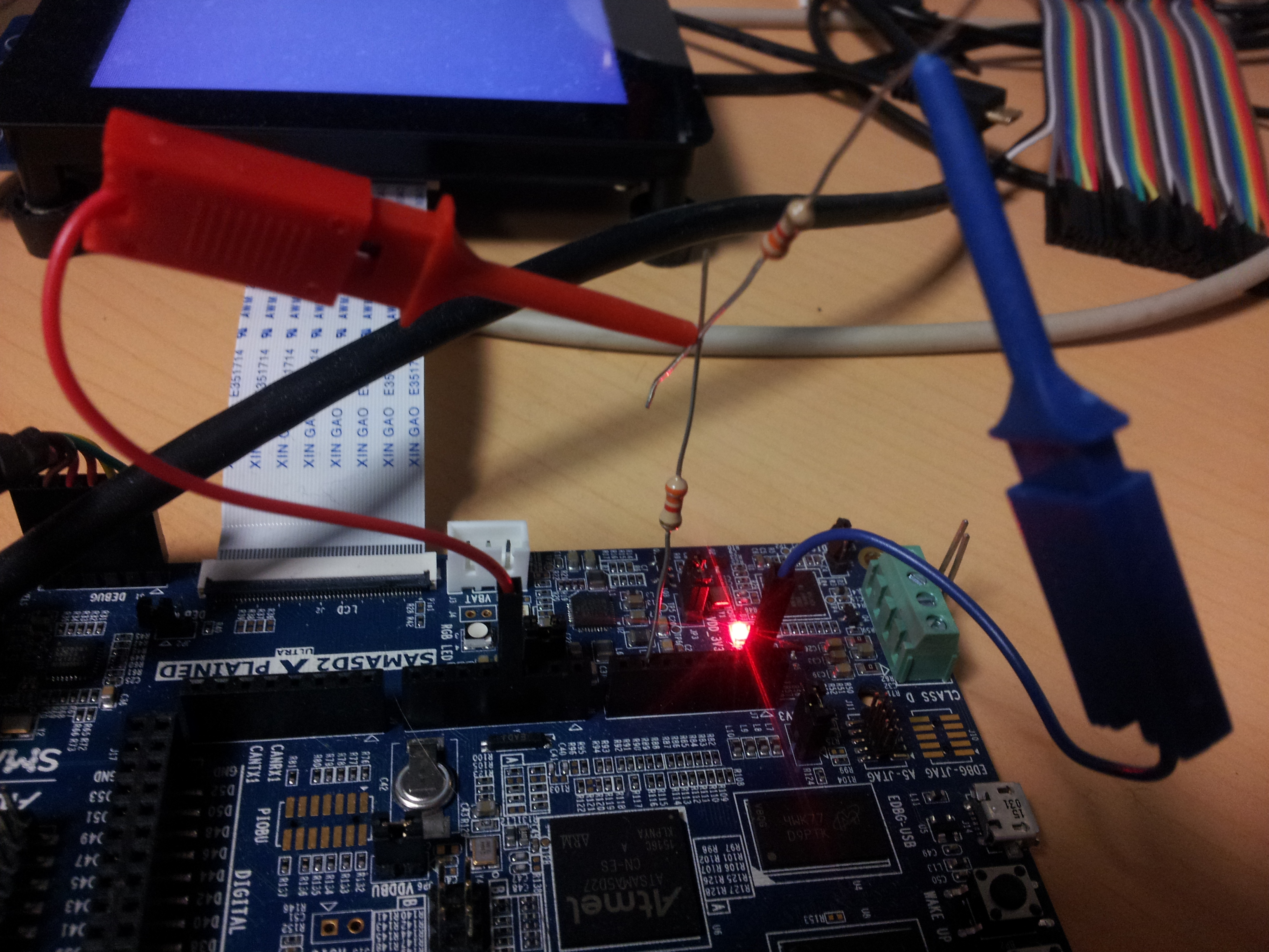
- Connect a waveform or DC generator to the pin 4 of J8 connector called A3. You can also use a resistor bridge as the image below shows
Test procedure
- request the conversion:
# cat /sys/bus/iio/devices/iio\:device0/in_voltage4_raw
3693
- request the scale:
# cat /sys/bus/iio/devices/iio\:device0/in_voltage_scale
0.805664062
- check the conversion by multiplying the conversion value with the scale:
3693 x 0.8 = 2954.4 mV
Signed differential channel conversion
Setup
Use A3 (AD4) and A6 (AD5) from J8 connectorTest procedure
- request the conversion:
# cat /sys/bus/iio/devices/iio\:device0/ in_voltage4-voltage5_raw
-396
- request the scale:
# cat /sys/bus/iio/devices/iio\:device0/in_voltage-voltage_scale
1.611328125
- check the conversion by multiplying the conversion value with the scale:
-396 x 1.6 = -633,6 mV
- you can compare it manually with the help of single ended conversions:
# cat /sys/bus/iio/devices/iio\:device0/in_voltage4_raw
1237
# cat /sys/bus/iio/devices/iio\:device0/in_voltage5_raw
2031
# cat /sys/bus/iio/devices/iio\:device0/in_voltage_scale
0.805664062

(1237-2031) x 0.8 = -635.2 mV
Hardware triggers
Hardware triggers are an operating mode of the ADC where conversions are no longer triggered by the software but directly by the hardware. For the SAMA5D2, currently there is one single type of hardware trigger, the external pin AD31, which on the Xplained board is connected on J17 pin 33 (labeled D52 on the PCB). Support for the hardware external trigger has been in kernel mainline since kernel 4.14 and in Linux4SAM releases since 5.7. Since kernel 4.14, we can use DMA to carry our data when using the hardware trigger. Check specific section for details.How it works
The external trigger is directly connected to the ADC inside the SoC. The ADC will monitor this pin once it's configured to do so. Once this pin will have edges (from logical 1 to logical 0 or the other way around), these will be detected by the ADC. Inside the device tree, one can configure if the ADC should react on rising edge (0->1), falling edge (1->0) or both type of edges. If an edge is detected, the ADC will start the conversion on all the enabled channels. As opposed to the software trigger which is done on demand by the user with a command (userspace process requesting it ), the hardware trigger and conversion occurs independently on the user. Thus, all the conversion data has to be stored in some buffer, for later retrieval by the userspace. This is why we need to setup a buffer and have an interface to read the data from, if we want to use the hardware trigger.API
IIO configuration of hardware triggers is also done through sysfs. Important folders in theiio:deviceX directory are: -
buffer -
trigger -
scan_elements
-
enabled: get and set the state of the buffer -
length: get and set the length of the buffer.
triggerX directories in /sys/bus/iio/devices/
Finally, scan_elements exposes 3 files per channel: -
in_voltageX_en: is this channel enabled? -
in_voltageX_index: index of this channel in the buffer's chunks -
in_voltageX_type: How the ADC stores its data. Reading this file should return you a weird looking string. How to interpret it is explained in the Going Further section
in_timestamp_* files.
How to set it up
Basically, what you should do for launching the hardware triggers is : Set up the channels in use (you can enable any combination of the channels you want)# echo 1 > /sys/bus/iio/devices/iio:device0/scan_elements/in_voltage0_en # echo 1 > /sys/bus/iio/devices/iio:device0/scan_elements/in_voltage1_en # echo 1 > /sys/bus/iio/devices/iio:device0/scan_elements/in_voltage2_en # echo 1 > /sys/bus/iio/devices/iio:device0/scan_elements/in_voltage3_enSet up the trigger we want to use (it must be the name of one of the triggers present in
iio/devices).
name sysfs file is there to inform you
# echo "fc030000.adc-dev0-external_rising" > /sys/bus/iio/devices/iio:device0/trigger/current_triggeror
# echo "fc030000.adc-dev0-external_falling" > /sys/bus/iio/devices/iio:device0/trigger/current_triggerfor instance.
# echo 100 > /sys/bus/iio/devices/iio:device0/buffer/lengthEnable the capture
# echo 1 > /sys/bus/iio/devices/iio:device0/buffer/enable
#
Now, all the captures are exposed in the character device /dev/iio:device0, with the following format
|
|||||||||||||||
poll() or select() on it to wait for data to arrive, and get them by reading the file, just like you would do with any other file.
And to stop the capture, just disable the buffer
# echo 0 > /sys/bus/iio/devices/iio:device0/buffer/enable
Testing the buffer
In the IIO documentation there is a tool that allows to do quick tests on the buffer from the command-line. The source code is located intools/iio/generic_buffer.c.
First, we need to compile it
arm-linux-gnueabi-gcc --static generic_buffer.c -o generic_bufferor
<path_to_cross-compiler/cross-compiler-prefix->-gcc --static generic_buffer.c -o generic_bufferor
cd tools
make iio
Then copy the
generic_buffer program on your board.
Below is an example of how to use this tool :
First, load the driver:
# modprobe at91-sama5d2_adcThen enable the channels:
# echo 1 > /sys/bus/iio/devices/iio:device0/scan_elements/in_voltage1_en
# echo 1 > /sys/bus/iio/devices/iio:device0/scan_elements/in_voltage3_en
Finally, the
generic_buffer tool does all the "enable" and "disable" actions for you.
You will only need to specify the IIO driver and the trigger you want to use (fc030000.adc and for the trigger fc030000.adc-dev0-external_rising for example).
You can also specify the buffer length to use (2 in this example). The default value is 128.
# ./generic_buffer -n fc030000.adc -t fc030000.adc-dev0-external_rising -l 2
iio device number being used is 0
iio trigger number being used is 0
/sys/bus/iio/iio iio/iio:device0 fc030000.adc-dev0-external_rising:

1681.420898 3296.777344
1841.748047 3296.777344
1841.748047 3296.777344
While running, it displays values that are stored in the buffer. So using the setup above, we have the following trace:
|
||||||||||||||
Going further
Understanding the in_voltageX_type file
Reading thein_voltageX_type file should return you something like: le:u10/16>>0 -
lerepresents the endianness, here little endian -
uis the sign of the value returned. It could be eitheru(for unsigned) ors(for signed) -
10is the number of relevant bits of information -
16is the actual number of bits used to store the datum -
0is the number of right shifts needed.
Using DMA to carry data on hardware trigger buffer
Starting from kernel 4.14, DMA support is available. By default, DMA is not used, if the watermark of the buffer is set to 1. In IIO context, the watermark is the point of length inside the buffer that once is reached, the buffer will start to throw results into userspace.With DMA activated, each conversion value is not transferred from memory to userspace, until the number of conversions reaches the watermark level. Once this number is achieved, all results are copied at once to userspace. This means that we can achieve a faster conversion rate, because we will not stop the system after each conversion (IRQ, copy_to_user, etc.), but once every 'watermark' conversions. To use the DMA support:
- Increase the buffer size to accommodate for more values:
echo 100 > /sys/bus/iio/devices/iio\:device0/buffer/length
- Configure watermark level:
echo 50 > /sys/bus/iio/devices/iio\:device0/buffer/watermarkThis means that the DMA will stop once 50 conversions are done (example), and then report the results. If a single edge is detected on the hardware trigger, we should not see any conversion results. This is normal. Linux is no longer interrupted on each trigger, and the DMA will carry the data and notify only when the watermark is reached. Once 50 edges happen, we should see all 50 results in bulk.
- How to check if DMA is enabled, and current watermark level :
cat /sys/bus/iio/devices/iio\:device0/hwfifo_enabled
cat /sys/bus/iio/devices/iio\:device0/hwfifo_watermark
- Which are the maximum and minimum values for the DMA watermark ? (actually the DMA buffers sizes )
cat /sys/bus/iio/devices/iio\:device0/hwfifo_watermark_min
cat /sys/bus/iio/devices/iio\:device0/hwfifo_watermark_max
Increasing ADC frequency to demonstrate DMA capabilities
Currently in the Device Tree for the ADC, we can see the minimum and the maximum clock for the peripheral. The DT properties describe which clock the ADC supports:atmel,min-sample-rate-hz = <200000>; atmel,max-sample-rate-hz = <20000000>;By default, the driver will pick the minimum sample rate of the clock. This means that 200kHz will be used, and we can do a sample with a delay of 21 clocks (datasheet), until the ADC capacitors are loaded. This means we can achieve a theoretical speed of around 8 kSamples/second. To achieve a better speed, we can increase the clock to 20 mHz, which is the maximum supported sample rate:
echo 20000000 > /sys/bus/iio/devices/iio:deviceX/sampling_frequencyWith this clock, we can push the ADC, DMA and kernel system to the limit and achieve a higher sampling speed. This could not be achieved if we did not use DMA, because the kernel would be interrupted for each conversion, and it would hog the CPU. During tests in our lab, we could manage to obtain 400kSamples/second until edges were lost.
Using digital oversampling for 1 or 2 more bits of precision
Starting with kernel 4.14 in our release linux4sam_6.0, oversampling can be used to achieve a better resolution for the ADC. Instead of 12 bits, we can use 14 bits. There is a slight ABI change with this support, from now on, reported data is always on 14 bits. This means that the conversion value is in range 0,16384. Without oversampling, the last 2 bits of data are always 0, thus if we shift to the right by 2 bits (or divide the value by 4), the obtained value is the same as before (12 bits, in range 0,4096). To enable oversampling for one extra bit of data, we can configure:echo 4 > /sys/bus/iio/devices/iio:deviceX/oversampling_ratioThis means that we can use 4 samples to get an additional bit. The ADC will do 4 measurements instead of a single one, and report a single value, the average of the 4, with an extra bit set.
echo 16 > /sys/bus/iio/devices/iio:deviceX/oversampling_ratioThis means that we can use 16 samples to get an additional bit. The ADC will do 16 measurements instead of a single one, and report a single value, the average of the 16, with two extra bits set.
cat /sys/bus/iio/devices/iio:deviceX/oversampling_ratio_availableTo restore the default behavior (no oversampling enabled), use:
echo 1 > /sys/bus/iio/devices/iio:deviceX/oversampling_ratio
| WebFaqBaseForm | |
|---|---|
| Boards | Sama5d29Curiosity, Sam9x75Curiosity, Sam9x60Curiosity, Sama7g5-ek, Sama5d2-icp, Sam9x60EK, Sama5d27WLSom1EK, Sama5d27Som1EK, Sama5d2PtcEK, Sama5d2Xplained |
| Components | Kernel, linux-5.15-mchp, linux-6.1-mchp, linux-6.6-mchp |
| Summary | Using the SAMA5D2-compatible ADC device |


|
|||||||||||||||
r27 - 28 May 2024 - 10:53:38 - AndreiSimion
Linux4SAM
Open source solutions ApplicationsBoards
- SAM9X75 Curiosity
- SAMA5D29 Curiosity
- SAM9X60 Curiosity
- SAMA7G5-EK
- SAMA5D2-ICP
- SAMA5D27 WLSOM1 EK
- SAM9X60-EK
- SAMA5D27 SOM1 EK
- SAMA5D2 PTC EK
- SAMA5D2 Xplained
- SAMA5D3 Xplained
- SAMA5D4 Xplained
- Older boards
FAQ
Useful links
- Microchip Microprocessors forums
- AT91 Community (archive)
- Microchip
- Linux4Microchip on GitHub
- Linux4SAM on GitHub
NAVIGATION
Copyright © by the contributing authors. All material on this collaboration platform is the property of the contributing authors.
Linux® is the registered trademark of Linus Torvalds in the U.S. and other countries.
Microchip® and others, are registered trademarks or trademarks of Microchip Technology Inc. and its subsidiaries. ![]()
Arm® and others are registered trademarks or trademarks of Arm Limited (or its affiliates). Other terms and product names may be trademarks of others.
Ideas, requests, contributions ? Connect to LinksToCommunities page.